Raspberry Pi Connection

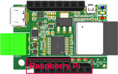
In order to user the adapter with a Raspberry Pi, it is flipped upside down and plugged directly onto the Raspberry Pi GPIO socket using the headers W2 and USRL.
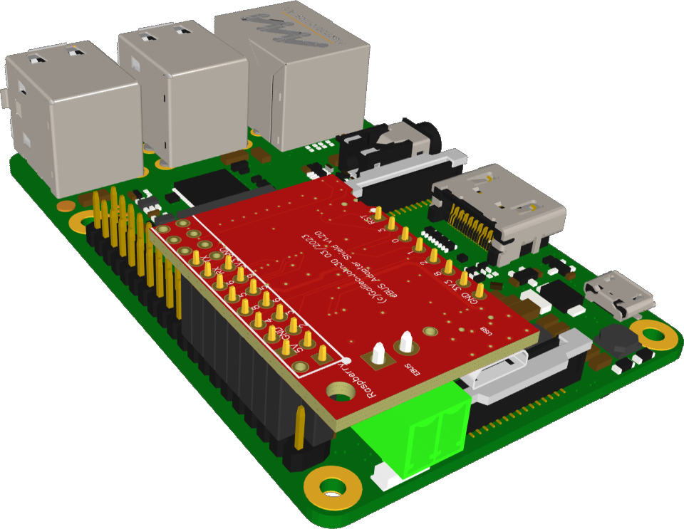
Attention: the headers on the adapter are shorter than the GPIO pins of the Raspberry Pi. Care must be taken here, that the socket closer to the hole (on the bottom left in the picture) is plugged into pin 2 of the Raspberry Pi GPIO headers, so that the hole is exactly above the one of the Raspberry Pi and a spacer could be placed in between.
When the adapter is plugged in (shown in red here for better visibility), it looks like this:

In case a cooler is used for the Raspberry Pi CPU, a stacking header like this or this has to be put in between or a Dupont cable needs to be used.
For Raspberry 5 with an older adapter, please also note the hint below.
The firmware automatically determines whether the adapter is plugged into a Raspberry Pi.
The adapter is supplied with power directly from the Raspberry Pi and communication takes place via the following pins on the Raspberry Pi GPIO:
- TxD: Pin 8 (GPIO 14)
- RxD: Pin 10 (GPIO 15)
These pins are assigned to the physical device “serial0”. The physical device is usually assigned to the logical device ttyAMA0, but depending on the Raspberry Pi version and the Raspbian / Raspberry Pi OS version different assignments may take place. The current configuration can be found by executing:
ls -l /dev
and then searching for the mapping of serial0. This is usually either ttyAMA0 or ttyS0.
Since the ttyS0 UART has difficulties with higher baudrates, it is strongly recommended to definitely use ttyAMA0 which is using UART type PL011 where these problems cannot occur.
If serial0 is connected to ttyS0, which occurs mainly with the Raspberry Pi 3 and some Raspbian/Raspberry Pi OS versions, then ttyS0 and ttyAMA0 can be swapped by adding an entry in /boot/config.txt:
dtoverlay=pi3-miniuart-bt
followed by a reboot.
The ebusd device configuration is therefore:
-d ens:/dev/ttyAMA0 --latency=50
The setting “latency=50” supports addressing potential timeout caused by some UART drivers of Raspberry Pi OS.
Configuration with Raspberry Pi OS
By default, the pins required for the eBUS adapter are used by the Raspberry Pi OS for a serial login shell. In order to be able to run the eBUS adapter via this interface instead, this login shell must be disabled.
Attention! If this shell is not completely disabled, it may send uncontrolled data to the eBUS, which may lead to a disruption of the entire bus system.
To disable the serial login shell, the following steps must be carried out (note that the text below may slightly vary depending on the Raspberry Pi OS):
- run
sudo raspi-config - select
Interface Options - select
Serial Port - answer
Would you like a login shell to be accessible over serial?with “No” - answer
Would you like the serial port hardware to be enabled?with “Yes” - exit “raspi-config” and reboot
Special UART settings
In some Raspberry Pi versions and/or Raspbian/Raspberry Pi OS versions, no UART is active by default. Therefore it should be checked whether in /boot/config.txt the entry
enable_uart=1
is included. Add if necessary and then reboot.
Attention! If the ttyebus driver is still present, it must be completely uninstalled (https://github.com/eBUS/ttyebus). This driver is not suitable for enhanced protocol.
To verify that the settings are correct, you can run dmesg|grep ttyAMA0, which should print a line like this, that should contain at least the UART PL011:
[ 1.138083] 20201000.serial: ttyAMA0 at MMIO 0x20201000 (irq = 81, base_baud = 0) is a PL011 rev2
Raspberry Pi 5
Due to different startup behaviour of GPIO pins on the Raspberry Pi 5 compared to earlier versions, the connection of GPIO 27 on the Raspi to IO9 of the adapter needs to be interrupted in order to use this combination.
Newer versions of the adapter have a shorter female header USRL (6 pins), so these are fine already, but for those with a longer female header (8 pins), the connection needs to be physically interrupted.
This can either be done
- by using a Dupont cable and leaving these two pins out or even all pins of USRL (safe variant), or
- by using a single row pin header omitting all pins of USRL (safe variant), or
- by bending the USRL header to the side so that no pins from USRL are connected when plugging onto the Raspi (potentially a bit harmful to USRL header).