Welcome to eBUS Adapter Shield v5!
This is the documentation of the eBUS Adapter Shield v5, which can be used to communicate with an eBUS enabled heating, ventilation or solar system.
Introduction
Version 5 of the eBUS adapter is a redesign of v3.1 with a significantly smaller footprint (37x26mm), pluggable eBUS connection, on-board WIFI due to changing to ESP32-C3, support for different Ethernet modules, and compatibility with many D1 mini shields (therefore the name “eBUS Adapter Shield”).
The adapter fulfils the arbitration times required by the eBUS specification just like v3.1 and v3.0.
This is made possible by the use of an ESP32-C3 in RISC architecture which, among other things, brings the following advantages:
- minimal time delay due to specially developed driver in the firmware
- full galvanic isolation with zero power drawn from eBUS (class 0 as of eBUS specification)
- flexible, configurable connection to the host:
- WIFI directly with onboard PCB antenna
- USB serial via integrated JTAG/serial interface
- Raspberry Pi via GPIO/ttyAMA0
- Ethernet with addon module USR-ES1 or another W5500 module
- full support for ebusd enhanced protocol and standard protocol
- via web browser configurable and also updatable firmware by OTA update as well as directly via USB JTAG/serial
- many further possibilities, e.g. connection with sensors and/or displays.
By using a DC-DC converter and galvanic isolation of the signals the eBUS is completely isolated from the host and only marginal current is drawn from the eBUS without any fluctuation (class 0 according to specification chapter 10.7).
This way, the heating, ventilation or solar system is perfectly protected and is not burdened in any way on its own power source.
Connections
This is an overview of the individual components and their connections:

- Heating/ventilation/solar thermal system
is connected to the adapter via a 2-wire cable (the polarity does not matter). - Adapter
connected to ebusd either via- WIFI (on board),
- USB (serial),
- GPIO (UART) of the Raspberry Pi, or
- Ethernet (with USR-ES1 or another W5500 module).
- ebusd
interprets the eBUS protocol and provides the data bidirectionally via MQTT, HTTP, KNX, and TCP port for Home-Assistant, KNX, Node-Red, FHEM, and others.
Host connection
Connecting via USB, WIFI, and Raspberry Pi is always possible. Only the Ethernet connection requires an additional W5500 module.
By using the easi> interface (via USB or network) all parameters can be adjusted.
Upon delivery, the firmware might need to be installed first, see under first steps.
The protocol between ebusd and the adapter is either the eBUS protocol directly (“standard protocol”) or the ebusd “enhanced protocol”. The enhanced protocol uses all advantages of the adapter by handling the eBUS arbitration directly from the firmware.
WIFI
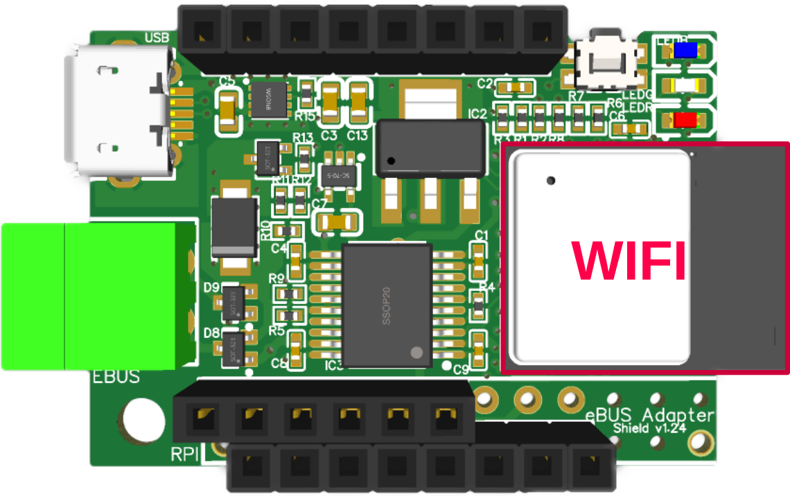
To use the adapter via WIFI, it just needs to be connected to a power source using the USB connector.
By using the easi> interface, the host connection needs to be set to WIFI (preset for a new or no yet configured adapter). It can also be used to adjust the WIFI configuration (SSID, DHCP/fix IP address, network mask, gateway).
The initial WIFI setting can be done either via the firmware page, the “EBUS” access point, or via WPS with push button mode (PBC; since firmware version 2024-10-27 as long as the adapter has not yet been configured and the button is pressed once so that the red LED is on permanently).
In addition to the adapter, only a regular USB cable with a Micro-B plug is needed. The adapter comes with an eBUS connector already plugged in.
The power is supplied directly via the USB connector, but it can also be powered via the pins on the socket W2, e.g. by using a DC Power Shield. See power source for details.
The ebusd device configuration is e.g. -d ens:192.168.178.2:9999, where 192.168.178.2 has to be replaced with the
right IP address.
USB
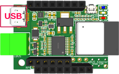
To use the adapter via USB, it just needs to be connected with the host using the USB connector.
All modern operating systems (Windows/Linux/MacOS) already have the necessary driver for that.
The adapter provides two interfaces on USB, that are presented as product “USB JTAG/serial debug unit” (idProduct: 0x1001) of “Espressif” (idVendor: 0x303a):
- Interface 0 (incl. 1): CDC ACM (USB “communication device class” with “abstract control model”)
the serial interface, appears as “USB ACM device” on Linux in/dev/ttyACM<x>, and as “USB JTAG/serial debug unit (interface 0)” or “Serial USB device (COM…)” on Windows - Interface 2: JTAG Debug
the Debug interface, does not appear as a device in/devon Linux (lsusb -treports it as “If 2, Class=Vendor Specific Class” without driver), and as “USB JTAG/serial debug unit (interface 2)” on Windows (this is unused)
By using the easi> interface, the host connection needs to be set to USB.
In addition to the adapter, only a regular USB data cable with a Micro-B plug is needed. The adapter comes with an eBUS connector already plugged in.
The power is supplied directly via the USB connector.
The ebusd device configuration is e.g. -d ens:/dev/ttyACM0, where ttyACM0 might be different when several
USB devices of this kind are connected.
Raspberry Pi
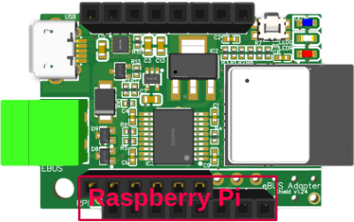
When flipping the adapter upside down, it can be plugged onto a
Raspberry Pi.
Care must be taken here, that the socket closer to the hole (on the bottom left in the picture) is plugged into pin 2 of the Raspberry Pi GPIO headers, so that the hole is exactly above the one of the Raspberry Pi and a spacer could be placed in between.
When the adapter is plugged in (shown in red here for better visibility), it looks like this:
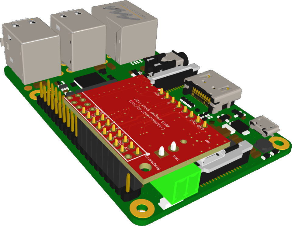
By using the easi> interface, the host connection needs to be set to Raspberry Pi. The firmware also detects this itself when booting and already configures the adapter accordingly.
For Raspberry Pi 5, an additional note must be taken into account for older adapters.
In addition to the adapter, only a stacking header might be needed in case the Raspberry CPU has a cooler on it. The adapter comes with an eBUS connector already plugged in.
The power is supplied directly via the Raspberry Pi GPIO socket.
The ebusd device configuration is: -d ens:/dev/ttyAMA0 --latency=50
Details on setting up the Raspberry Pi can be found here.
Ethernet
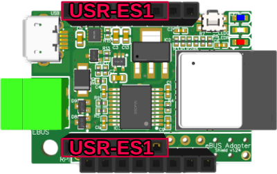
To use the adapter via Ethernet, the following options are available:
- USR-ES1 Module with W5500 (e.g. from here or here) to plug into W1+USRL,
- W5500 Ethernet module (e.g. from here or here) to plug flipped into USRL+W2 (so that the 5V pin of the module is in W2/9).
Attention: when the W5500 module is not correctly plugged onto the adapter (e.g. shifted or in the wrong direction), the adapter can be damaged and become unusable! So the best way it to disconnect power, plug in the module, and check the position. After that, power can be reconnected.
When a USR-ES1 module is plugged in, it looks like this:
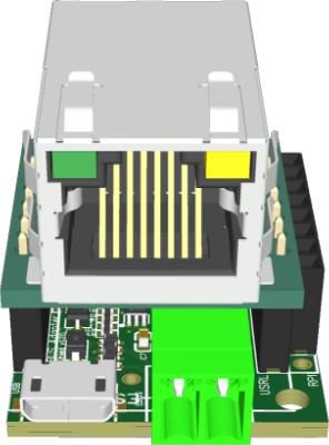
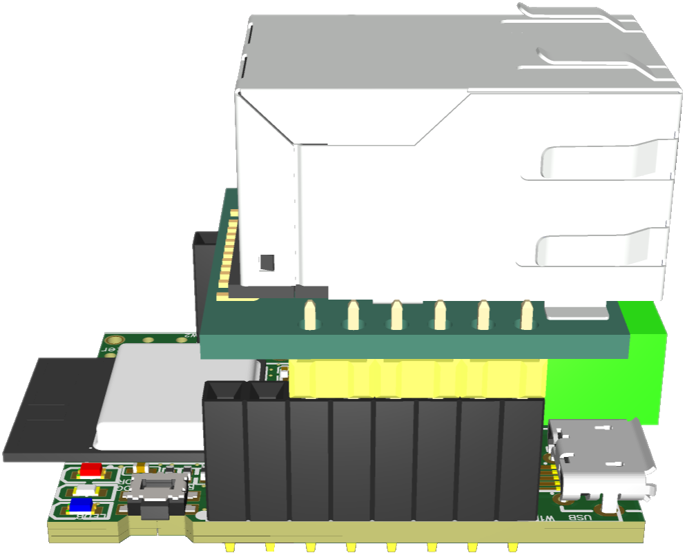
By using the easi> interface, the host connection needs to be set to Ethernet. It can also be used to adjust the Ethernet configuration (DHCP/fix IP address, network mask, gateway).
If the W5500 module cannot be detected by the firmware, it might be broken or ideally only the pin connection is not stable. See here for checking this.
In addition to the adapter and the Ethernet module, only a regular USB cable with a Micro-B plug is needed. The adapter comes with an eBUS connector already plugged in.
The power is supplied directly via the USB connector, but it can also be powered via the pins on the socket W2, e.g. by using a DC Power Shield. See power source for details.
The ebusd device configuration is e.g. -d ens:192.168.178.2:9999, where 192.168.178.2 has to be replaced with the
right IP address.
Power Source
When using Ethernet or WIFI as the host connection, the adapter is simply powered via the USB connector using a standard USB power adapter, e.g. one that can also be used to charge a cell phone.
The minimum requirement for the power source is 1 Watt. To be on the safe side, we recommend using a power source with at least 2 Watts, i.e. capable of supplying 400mA at 5V.
Alternatively, the adapter can also be powered via the pins on the socket W2, e.g. by using a DC Power Shield.
Pin headers, functions
Additional pin headers are available for connecting further components. With Ethernet only a small number of pins are available for that.
| Connector | Function | USB | WIFI | Raspberry Pi | Ethernet |
|---|---|---|---|---|---|
| USB | USB connector | USB | power | - | power |
| W1 | I/O / W5500 | I/O | I/O | I/O | W5500 |
| W2 | I/O / Raspi | I/O | I/O | Raspi | I/O |
| USRL | W5000 / Raspi | - | - | Raspi | W5500 |
| EBUS | eBUS connector | eBUS | eBUS | eBUS | eBUS |
Legend:
- - = not usable otherwise
The easi> interface can be used to associate a pin with an I/O function.
I/O pinout
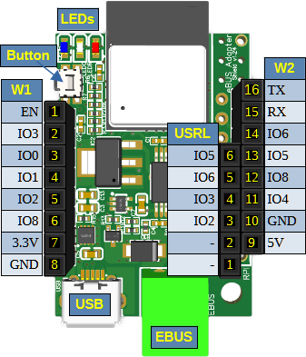
The ESP32-C3 I/O pins are associated and available on headers as follows:
| IO | Function / Header/Pin | Setting | USB + WIFI | Raspberry Pi | Ethernet |
|---|---|---|---|---|---|
| 0 | W1/3 | * | * | MISO | |
| 1 | W1/4 | * | * | RST | |
| 2 | W1/5, USRL/3, RPI/5 | pull-up | * | SCL | MOSI |
| 3 | W1/2, USRL/4, RPI/7 | * | GPIO4 | SCLK | |
| 4 | W2/11, RPI/8 | * | TXD | * | |
| 5 | W2/13, USRL/6, RPI/11+12 | * | GPIO17+18 | INTN | |
| 6 | W2/14, USRL/5, RPI/G | * | GND | SCNN | |
| 7 | eBUS RX | - | - | - | |
| 8 | W1/6, W2/12, RPI/10 | pull-up | * | RXD | 3.3V |
| 9 | Button, LED blue, RPI/13 | pull-up | - | (GPIO27) | - |
| 10 | eBUS TX | - | - | - | |
| 18 | USB- | USB | - | - | |
| 19 | USB+ | USB | - | - | |
| 20 | RX, LED green, W2/15, RPI/16 | LED+* | GPIO23+LED+* | LED+* | |
| 21 | TX, LED red, W2/16, RPI/18 | 500R | LED+* | GPIO24+LED+* | LED+* |
| EN | Reset, W1/1 | pull-up | Reset | Reset | Reset |
Legend:
- * = any function assignment
- - = not usable otherwise
LEDs
The adapter has 3 LEDs with the following assignment:
- blue: signals from firmware
- green: eBUS receive or firmware signal
- red: eBUS send or firmware signal
During boot all LEDs fade three times. In that phase, pressing the button allows to ignore all saved settings and start the WIFI access point with SSID “EBUS”.
In eBUS mode, the blue LED blinks shortly every 5 seconds as a ping, when configured like that via easi> interface.
The LEDs light up green and red on the corresponding eBUS traffic (green for receive, red for send), when eBUS mode is on and configured like that via easi> interface.
Button
The adapter has a button on board allowing several actions:
- press+hold before powering up:
bootloader mode - press+hold during boot (while the LEDs fade):
ignore all saved settings and start the WIFI access point “EBUS” - press after boot:
- as long as the adapter has not yet been configured: start WPS in push button mode (PBC, red LED is on permanently until successfully connected)
- otherwise: red LED fades once
- press+hold after boot:
reboot
In additional to that, the button can be used to check the power supply as well, as pressing it will power on the blue LED independent of the ESP I/O.
Additional functions
Many of the D1 mini Shields are compatible with the adapter and can simply be plugged in. The pin on the top left of such a module is intentionally left out and will “hang out”, so the module needs to sit exactly on the 8 pins of the header W2 and is thus shifted by one pin on W1.
The following shields are usable:
- OLED 0.66 Shield: tested successfully
- BMP280/BME280/BMP180: tested successfully
- 8x8 RGB Shield: tested successfully
- DC Power Shield: tested successfully
With this you can use almost any DC plug-in power supply with a 5.5mm barrel connector to provide the power supply instead of via USB. - RGB LED Shield
- PIR Shield (*)
- SHT30 Shield (*)
- DHT Shield (*)
(*) planned for a future firmware version
The association of the ESP32-C3 pins with the Wemos / shield ports D0-D8 + A0 is this:
| Wemos | IO | W1 | Adapter | W2 | IO | Wemos |
|---|---|---|---|---|---|---|
| RST | - | 16 | IO21 | TX | ||
| A0 | EN | 1 | 15 | IO20 | RX | |
| D0 | IO3 | 2 | 14 | IO6 | D1 | |
| D5 | IO0 | 3 | 13 | IO5 | D2 | |
| D6 | IO1 | 4 | 12 | IO8 | D3 | |
| D7 | IO2 | 5 | 11 | IO4 | D4 | |
| D8 | IO8 | 6 | 10 | GND | GND | |
| 3V3 | 3.3V | 7 | 9 | 5V | 5V |
Due to the many pins occupied by the W5500 module, with Ethernet only some shields are usable directly. I2C-based shields and those with at most 3 I/O pins can be connected to W2 via IO4, IO20, and IO21 (e.g. via Dupont cable).
Links
Here are some links that contribute to the topic or contain basic information:
