Welcome to eBUS Adapter 3.0!
This is the documentation of the eBUS adapter v3.0, which can be used to communicate with an eBUS enabled heating, ventilation or solar system.
Introduction
Version 3 of the eBUS adapter fulfils the arbitration times required by the eBUS specification for the first time.
This is made possible by the use of a PIC which, among other things, brings the following advantages:
- minimal time delay due to hardware-related programming
- flexible, configurable variants for connecting to the host:
- USB serial via CP2102 (onboard)
- Raspberry Pi via GPIO/ttyAMA0
- WIFI via LOLIN/Wemos D1 mini with ESP-8266 or via Wemos C3 mini with firmware of v5
- Ethernet via USR-ES1 module with W5500
- full support for ebusd enhanced protocol and standard protocol
- updatable firmware using a serial bootloader
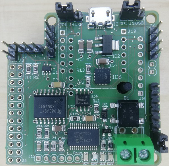
In order to be able to get all these options on a 5cm x 5cm board, almost only SMD is used:

The SMD technology also offers some advantages:
- high packing density
- all variants on one board
- cheap assembly
Two of the variants also offer the option of connecting sensors and/or displays.
By using a DC-DC converter and galvanic isolation of the signals the eBUS is completely isolated and only marginal current is drawn from the eBUS without any fluctuation (class 0 according to specification chapter 10.7).
Connections
This is an overview of the individual components and their connections:

- Heating/ventilation/solar thermal system
is connected to the adapter via a 2-wire cable. - Adapter
connected to ebusd either via- USB (UART),
- GPIO (UART) of the Raspberry Pi,
- WIFI (Wemos) or
- LAN (USR-ES1 module with W5500).
- ebusd
interprets the eBUS protocol and provides the data bidirectionally via MQTT, HTTP, KNX, and TCP port for Home-Assistant, KNX, Node-Red, FHEM, and others.
Variants
USB support is built into all variants, as an CP2102 is always assembled directly on the board. This is necessary, to e.g. update the PIC firmware or to adjust the Ethernet configuration.
The corresponding variant is set via ebuspicloader (or J12).
The protocol between ebusd and the adapter is either the eBUS protocol directly (“standard protocol”) or the ebusd “enhanced protocol”. The enhanced protocol uses all advantages of the adapter by handling the eBUS arbitration directly from the PIC firmware.
Note for high-speed enhanced mode:
For the enhanced protocol, a high-speed variant may be used for serial connections (USB, RPI and WIFI) that avoids
unnecessary delays due to the transfer from/to ebusd (or ESP).
This can be activated by adjusting the variant.
The ebusd device configuration then needs to be changed from enh: prefix to ens: prefix for direct serial
connections (i.e. USB or RPI).
For WIFI, the ESP firmware needs to be configured accordingly and the ebusd device configuration remains at enh:.
USB

To use the adapter via USB, just connect J2 with your host.
The jumpers have to be set as follows:
- J1: USB
- J4: USB
- J12: Pins 1-2 for enhanced protocol, optional see here
- J12: Pins 6-7 for high-speed (enhanced), optional see here
The power is supplied directly via the USB connector J2 on the adapter.
The ebusd device configuration is e.g. -d enh:/dev/ttyUSB0, where ttyUSB0 might be different when several
USB serial devices are connected.
For high-speed enhanced mode, see the hint above.
Raspberry Pi

Using an at least 2x9 socket J8, the adapter can be plugged onto the
Raspberry Pi directly.
The jumpers have to be set as follows:
- J1: RPI
- J4: RPI
- J12: Pins 1-2 for enhanced protocol, optional see here
- J12: Pins 6-7 for high-speed (enhanced), optional see here
The power is supplied directly via the Raspberry Pi GPIO socket J8.
The ebusd device configuration is: -d enh:/dev/ttyAMA0 --latency=50
For high-speed enhanced mode, see the hint above.
Details on setting up the Raspberry Pi can be found here.
WIFI

By plugging a LOLIN/Wemos D1 mini with ESP-8266
or a Wemos C3 mini with firmware of v5
onto socket J9, the adapter can be used via WIFI.
The jumpers have to be set as follows for LOLIN/Wemos D1 mini:
- J1: RPI
- J4: open (or set to RPI)
- J12: Pins 1-2 for enhanced protocol, optional see here
- J12: Pins 4-5 (WIFI mode), optional see here
- J12: Pins 6-7 for high-speed (enhanced), optional see here
For Wemos C3 mini with firmware of v5, the jumpers have to be set as follows though:
- J1: RPI
- J4: open (or set to RPI)
- J12: needs to remain open (no jumper)
The power is supplied directly via the USB connector of the Wemos.
Attention: The Wemos are incredibly delicate with regard to the power supply! A variety of effects come up when the power supply is insufficient, e.g. reboots, or no connection at all, or only poor and unstable connection to the Access Point.
The Wemos are quite sensitive to any RF interference due to the tiny antenna. Therefore, a good to very good signal (at least 70%) is required for a stable connection. It can also help to put some distance between the Wemos and the adapter with the two included 1x8 headers.
The Wemos has to be flashed with a suitable firmware, e.g. ebusd-esp (starting from version 22.11.2020). ebusd-esp has to be configured to “Adapter 3.0 RX+TX” or “Adapter 3.0 RX+TX high-speed” if enabled.
The ebusd device configuration is e.g. -d enh:192.168.178.2:9999, where 192.168.178.2 has to be replaced with the
right IP address.
For high-speed enhanced mode as transfer between the adapter and ebusd-esp, see the hint above.
Ethernet

By plugging a USR-ES1 modul with W5500 onto socket J10,
the adapter can be used via LAN.
The jumpers have to be set as follows:
- J1: RPI
- J4: USB
- J12: Pins 1-2 for enhanced protocol, optional see here
- J12: Pins 5-6 (Ethernet mode), optional see here
The power is supplied directly via the USB connector J2 on the adapter.
The Ethernet configuration (IP address, network mask, gateway) is done via the bootloader in the PIC through the USB port J2, see here: Ethernet configuration. By default, it is configured for DHCP and the adapter appears with a host name prefix of “aebus3” in the router.
The ebusd device configuration is e.g. -d enh:192.168.178.2:9999, where 192.168.178.2 has to be replaced with the
right IP address (ebusd enhanced high-speed mode is irrelevant for network-based transport).
The PIC firmware sets the MAC address of the adapter in the LAN to AE:B0:53:XX:XX:XX, where the XX depend on the ID of
the PIC (AEB053 stands for “Adapter eBUS 3”).
Jumpers/pin headers, functions
In the variants with Wemos and Raspberry Pi, additional pin headers are available for connecting further components.
| Connector | Function | USB | Raspberry Pi | WIFI | Ethernet |
|---|---|---|---|---|---|
| J1 | Jumper TX | USB | RPI | RPI | RPI |
| J2 | USB connector | USB connector | - | power connector | power connector |
| J3 | Gas sensor/switch | - | Gas sensor | Gas sensor | - |
| J4 | Jumper POWER | USB | RPI | (RPI) | USB |
| J5 | I2C | - | I2C | (I2C)* | - |
| J6 | I2C | - | I2C | (I2C)*+ext | - |
| J7 | 1wire sensor | - | 1wire sensor | 1wire sensor | - |
| J8 | RPi GPIO connector | - | Raspberry Pi | - | - |
| J9 | Wemos connector | - | - | Wemos D1 mini | - |
| J10 | USR-ES1 connector | - | - | - | USR-ES1 W5500 |
| J11 | PIC PROG | - | - | - | - |
| J12 | PIC AUX | PIC AUX | PIC AUX | PIC AUX | PIC AUX |
| J13/J14 | eBUS connector | eBUS | eBUS | eBUS | eBUS |
* To the points in brackets:
- I2C is currently not yet supported by the ebusd-esp firmware.
- with WIFI, J4 can be left out or set to RPI.

PIC AUX J12
This connector holds pins of the PIC and their assignment and usage depends entirely on the PIC firmware, see PIC Firmware.
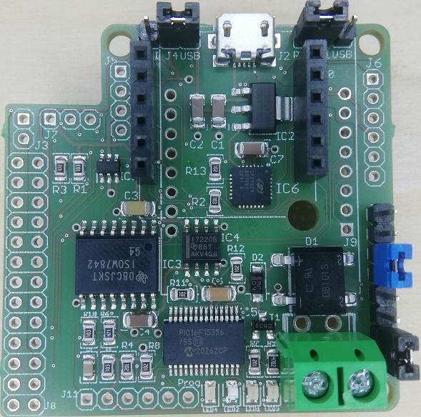
Important note: The pins at J12 must never be connected to any pin on the other jumpers/pin headers/sockets as separate power sources are used here. Any connection endangers the adapter and devices on the eBUS!
Here is a picture showing the two isolated halves of the board: red for eBUS and green for USB etc.:

PIC PROG J11
The PIC programming connector J11 allows updating the Firmware of the PIC including the bootloader with an appropriate programming device. This should only be necessary in rare cases, as the PIC was programmed before delivery and can be updated with newer firmware via the embedded bootloader. For more details, see PIC Firmware.
Additional functions
J3 Gas sensor/switch
J3 can be used to connect a gas sensor or simple switch with the following pins:
- GND
- Signal: Wemos D7 / RPI Pin 18 GPIO 24
J5 I2C
J5 can be used to connect I2C devices (e.g. OLED SSD1306 or Nextion) with the following pins:
- SDA: Wemos D2 / RPI Pin 3 GPIO 2 (SDA)
- SCL: Wemos D1 / RPI Pin 5 GPIO 3 (SCL)
- +3.3V
- GND
J6 I2C
J6 can be used to connect I2C devices (e.g. OLED SSD1306 or Nextion) and on WIFI further devices with the following pins:
- SDA: Wemos D2 / RPI Pin 3 GPIO 2 (SDA)
- SCL: Wemos D1 / RPI Pin 5 GPIO 3 (SCL)
- GND
- +3.3V
- D5: Wemos D5
- A0: Wemos A0
J7 1wire Sensor
J7 can be used to connect 1wire devices (e.g. temperature sensor DS18B20) with the following pins:
- +3.3V
- Signal: Wemos D6 / RPI Pin 7 GPIO 4 (4.7kOhm pull up)
- GND
LEDs
The adapter has 4 LEDs with the following assignment:
- yellow: power supply PIC
- blue: signals from PIC
- green: eBUS receive
- red: eBUS send
The PIC is only supplied with power and can work at all when the yellow LED lights up. The green and red LEDs light up on the corresponding eBUS traffic and the green one lights up permanently if the eBUS line is not yet connected or the voltage level on the eBUS line is too low. The blue LED is controlled by the PIC firmware, which is described here.
Links
Here are some links that contribute to the topic or contain basic information:
- eBUS specification (physikal layer OSI 1)
- Reichelt cart for pin headers/connectors:
- the short pin headers and jumpers are for J1, J4, J11 and J12 (1x6 to be split into 2 pieces of 1x3 each, 1x14 to be split into 1x8 + 1x6)
- the 1x6 female headers are for J10
- the long pin headers are for J3, J5, J6 and J7
- ebusd-esp firmware for Wemos D1
- ebusd wiki