Extension Board
The extension board is designed for being plugged onto the base board. It allows using a variety of sensors such as air pressure, humidity and temperature, as well as displays, gas meter, etc. A buzzer my be connected as well for alarm output.
You can also experiment with the extension board when using it standalone, ie. without eBUS connection. This makes it easy to connect sensors or displays to the Wemos.
Construction

The number of components is a lot less compared to the base board and it consists mainly of female and male headers for connecting Wemos, displays, and sensors.
The power is supplied directly to the C-connector of the Wemos via a USB power supply.
Part List
The necessary parts are listed here.
Assembly
The board is not lead free manufactured (HASL), so it can be soldered with normal leaded solder. This is still legally allowed for private use as well as partly for commercial purposes.
The assembly of the extension board is carried out just as the base board according to usual rules, i.e. flat components first followed by the higher ones in layers as follows:
- SMD switch (only for v2.0)
- Resistors
- Flat sockets
- Capacitors
- Switch
- Socket headers
- LEDs
- Pin headers on the back for plugging onto base board
- Plug in the Wemos D1 with its pin headers
Before soldering the resistors, be sure to check the resistance values with an ohm meter to avoid misplacing them.
Important hints for version 2.0:
- The two SMD buttons are a bit tricky and it is sufficient to use S3 only since the function of S2 is already provided by the S1 switch:
- Place the SMD button with a finger and press it lightly (or press it with some light weight).
- Then solder the already tinned soldering surface with the other hand.
- Once the button is tidy, solder the second pin as usual and afterwards optionally solder the first pin again if needed.
Important hints for all versions:
- The LEDs sit on spacers, which are also a kink protection.
If you are using a clear case, the space should also match so that the LEDs are slightly higher than the top of the Wemos. - You can exclude the UART sockets completely, since usually a Wemos is used.
Assembly variants
The possible application variants are described here.
Depending on the desired application many assembly variants are possible. In particular, one should consider before soldering, whether and how for example BME280, OLED, Nextion, gas meters, NTC, Buzzer, etc. are to be connected.
If, for example, a BME280 is to be used outside the housing for measuring temperature etc., a 4-wire cable is required which is connected via a pin header, socket header, or directly to the extension board. Depending on this, the corresponding socket and/or pin headers have to be selected and soldered.
The jumper assignment depends on the variant used as well.
Assembly of LEDs
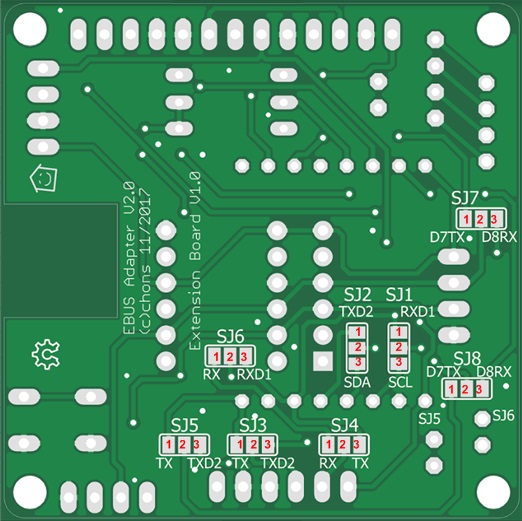
Soldering the extension board

Assembled and soldered board (v2.0).

View from the back (v2.0) with jumpers and pin headers for connection to the base board.
Finished extension board

That’s how the finished extension board (v2.1) looks like when plugged onto the base board including Wemos with ESPEasy and directly attached BME280.
On the left is the Dupont cable for the connection to the Wemos with ebusd-esp.
Jumper Function Matrix

Older versions are here: v2.1 v2.0
On the back of the extension board there are some jumpers (solder bridges) that allow different assignments depending on the desired sensors or used Wemos firmware.
Depending on the desired application variant for the extension board, the jumpers have to be taken care of as otherwise the sensors won’t work.
Important: The Wemos with ESPEasy may not be jumpered to RX and TX, as otherwise the signals from the simultaneously connected Wemos would be grounded with ebusd-esp!
Such errors may not seem to make any difference at first, but certainly show up once several devices are connected to the eBUS.
Jumper für Version 2.2
| Sensor | Wemos PINs | SJ2 | SJ1 | SJ4 | SJ3 | Comment |
|---|---|---|---|---|---|---|
| ebusd-esp | RX/TX | 3-2 | 3-2 | only for using ebusd-esp directly on the extension board! | ||
| ebusd-esp | D5/D4 | 2-1 | 2-1 | only for using ebusd-esp directly on the extension board! | ||
| ESPEasy | open | open | ||||
| JP6 BME280 | D1/D2 | |||||
| JP7 Buzzer | D0 | |||||
| JP3 OLED | D1/D2 | |||||
| JP2 Nextion | D8/D7 | 3-2 | 3-2 | |||
| JP2 Nextion | RX/TX | 2-1 | 2-1 |
- Recommended settings are in bold.
3-2means: connect the left soldering point to the middle one.2-1means: connect the middle soldering point to the right one.
Example 1: in case a Wemos with with ESPEasy and a BME280 shall be connected, no jumpers have to be set.
Example 2: in case a Wemos with ebusd-esp shall be used directly on the extension board, the jumpers SJ4/SJ3 have to be connected as stated in the table.
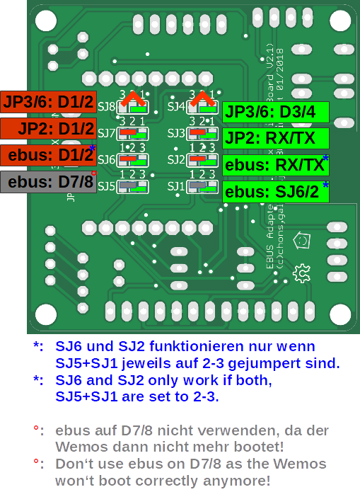
Jumper for version 2.1
Attention: the layout of SJ8+SJ4 is wrong, as the originally middle pin is placed on the right!
| Sensor | Wemos PINs | SJ8 | SJ4 | SJ7 | SJ3 | SJ6 | SJ2 | SJ5 | SJ1 | Comment |
|---|---|---|---|---|---|---|---|---|---|---|
| ebusd-esp | RX/TX | 2-3 | 2-3 | 2-3 | 2-3 | only for using ebusd-esp directly on the extension board! | ||||
| ESPEasy | open | open | ||||||||
| BME280 | D1/D2 | 3-1 | 3-1 | |||||||
| BME280 | D3/D4 | 2-1 | 2-1 | |||||||
| Buzzer | D0 | |||||||||
| OLED | D1/D2 | 3-1 | 3-1 | |||||||
| OLED | D3/D4 | 2-1 | 2-1 | |||||||
| Nextion | RX/TX | 2-1 | 2-1 |
- Recommended settings are in bold.
1-2and3-2mean: connect the left soldering point to the middle one (pay attention to different order e.g. SJ7 compared to SJ6).2-3and2-1mean: connect the middle soldering point to the right one (pay attention to different order e.g. SJ7 compared to SJ6).3-1means: connect the left soldering point to the right one (only for SJ8+SJ4).
Example 1: in case a Wemos with with ESPEasy and a BME280 shall be connected, the jumpers SJ8 and SJ4 both have to be connected on pin 3 and 1 and the jumpers SJ5 and SJ1 remain open.
Example 2: in case a Wemos with ebusd-esp shall be used directly on the extension board, the jumpers SJ6/SJ2 and SJ5/SJ1 have to be connected as stated in the table.
Jumper for version 2.0
Attention: the label on SJ2+SJ1 is exchanged, so SDA+SCL are on the top (not on the bottom)!
| Sensor | Wemos PINs | SJ2 | SJ1 | SJ3 | SJ4 | SJ5 | SJ6 | SJ8 | SJ7 | Comment |
|---|---|---|---|---|---|---|---|---|---|---|
| ebusd-esp | RX/TX | 1-2 | 1-2 | 1-2 | 2-3 | only for using ebusd-esp directly on the extension board! | ||||
| ESPEasy | open | open | ||||||||
| BME280 | D1/D2 | 1-2 | 1-2 | |||||||
| Buzzer | D0 | |||||||||
| OLED | D1/D2 | 1-2 | 1-2 | |||||||
| Nextion | RX/TX | 1-2 | 1-2 |
- Recommended settings are in bold.
1-2means: connect the left or top soldering point to the middle one (i.e. 1 with 2 in the picture above).2-3means: connect the middle soldering point to the right or bottom one (i.e. 2 with 3 in the picture above).
Example 1: in case a Wemos with with ESPEasy and a BME280 shall be connected, the jumpers SJ2 and SJ1 both have to be connected on pin 1 and 2 and the jumpers SJ8 and SJ7 remain open.
Example 2: in case a Wemos with ebusd-esp shall be used directly on the extension board, the jumpers SJ5/SJ6 and SJ8/SJ7 have to be connected as stated in the table.
Jumpers when fully equipped

This image shows a variant with full configuration: the base board with Wemos ebusd-esp, the extension board with ESPEasy and a BME280 sensor for temperature, humidity, and pressure.
In this variant no jumpers have to be set for the Wemos with ebusd-esp, since it is attached to connector JP8 and this directly has both, the RX and TX signal.
The Wemos with ESPEasy is plugged onto the expansion board and thus uses all the pin headers provided. If ESPEasy is located on the extension board and is connected to the BME280 sensor, no jumpers (v2.2) or jumpers SJ8/SJ4 (v2.1) or SJ2/SJ1 (v2.0) have to be set.
Jumpers fully equipped for version 2.2
For version 2.2, no jumper has to be set for the fully equipped variant described above and the I2C settings on ESPEasy can remain on default (D1/D2).
Jumpers fully equipped for version 2.1
| Sensor | Wemos PINs | SJ8 | SJ4 | SJ7 | SJ3 | SJ6 | SJ2 | SJ5 | SJ1 |
|---|---|---|---|---|---|---|---|---|---|
| BME280 | D3/D4 | 2-1 | 2-1 | ||||||
| OLED | D3/D4 | 2-1 | 2-1 |
Attention: With these jumper settings for v2.1, the I2C settings on ESPEasy have to be changed to D3/D4.
Jumpers fully equipped for version 2.0
| Sensor | Wemos PINs | SJ2 | SJ1 | SJ3 | SJ4 | SJ5 | SJ6 | SJ8 | SJ7 |
|---|---|---|---|---|---|---|---|---|---|
| BME280 | D1/D2 | 1-2 | 1-2 | ||||||
| OLED | D1/D2 | 1-2 | 1-2 |
With these jumper settings for v2.0, the I2C settings on ESPEasy can remain on default (D1/D2).